MECH-018 to 22 weeks
Design-build
One contract from load calculation to commissioning.
Documented at handover
- Load calculation with the assumptions listed
- Equipment schedule with model numbers and selection points
- As-built drawings
Demonstration site. Blueprint Mechanical is not a real contractor. Licence number, phone numbers and address are placeholders.
Commercial and residential HVAC engineering in Denver. Manual J load calculations, documented installs, and systems that actually get commissioned.
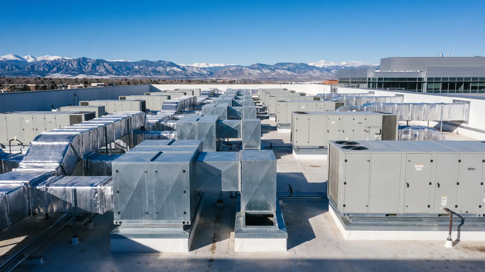
Every catalogue in this industry is written at sea level. Denver is not at sea level, and the gap between those two facts is where most undersized systems in this city come from.
Check any proposal you have been given. If it does not mention altitude, it was priced at sea level, and the equipment on it is probably the wrong size.
5,280ft
Site elevation we design for. Air here is about 17 percent thinner, so the sensible heat constant falls from 1.08 to roughly 0.90.
1°F
Denver heating design condition at 99.6 percent. Heat pumps get selected on capacity here, not at the 47 °F rating point.
48
Engineers, fabricators and service technicians. NATE certified, EPA 608 Universal.
2009
Designing, building and commissioning mechanical systems on the Front Range.
Service schedule
Nine service lines. Each one has a written scope, a typical programme, and a list of the documents you hold at handover. Open a folder to read the specification.
One contract from load calculation to commissioning.
Documented at handover
Packaged RTU replacement, curb adaptation and controls.
Documented at handover
Heat recovery VRF where zoning and part load matter.
Documented at handover
Condensing plant, hydronic loops and slab radiant.
Documented at handover
Designed to a friction rate. Fabricated in our own shop.
Documented at handover
BACnet controls, sequences written down before they are programmed.
Documented at handover
MECH-02 · Rooftop systems
A 20 ton packaged unit serving three VAV zones, drawn the way we would issue it. Move the lens over the drawing to read duct sizes, airflows and terminal schedules, or use the stepper to walk through the seven labelled components one at a time.
This is the level of detail that goes into a proposal before anyone talks about price. Sizes are stated, not implied. Static pressure is calculated, not assumed. The economizer has a changeover strategy rather than a hope.
MECH-01 · Design-build
One contract, five stages, and a document at the end of each one. Nothing gets ordered before the load is calculated, and nothing gets handed over before it is balanced.
We walk the building, measure what is there, and run the load. Assumptions listed, so you can argue with them.
Load calculation report
Manual S selection against the calculated load, corrected for 5,280 ft. Two or three options priced honestly.
Equipment schedule
Duct and pipe designed to a stated friction rate, with the total effective length recorded rather than assumed.
Layout and shop drawings
Fittings cut in our own shop to the drawing, then installed to the programme we agreed at award.
As-built drawings
Airflows and water flows measured against design, adjusted until they match, and written down.
TAB and commissioning report
Every case study below lists the measured result, not an adjective. Where we improved something, the reading before and the reading after are both there.
Measured fan energy down 31 percent. No tenant lost a working day.
Read the case study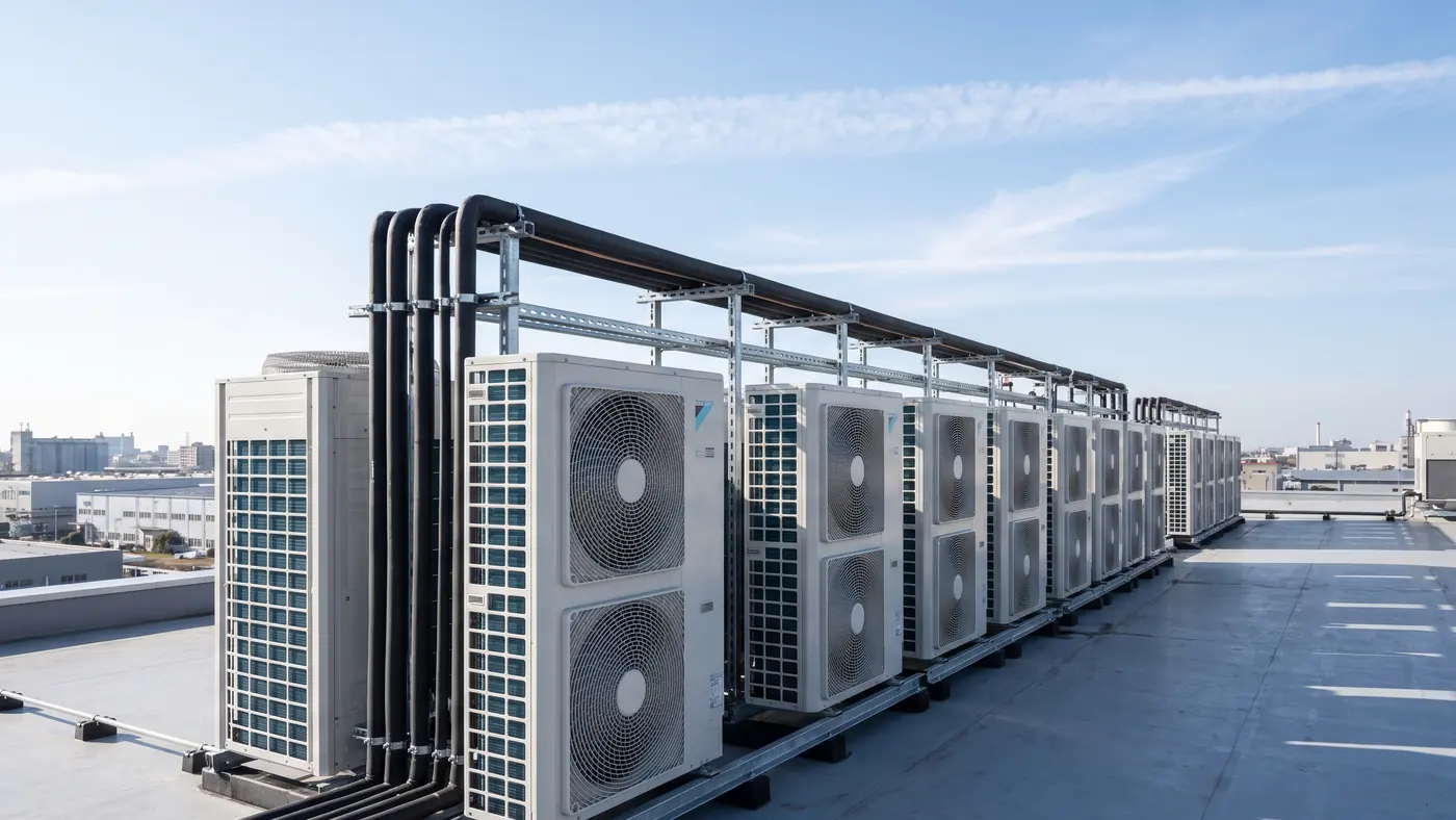
Simultaneous heating and cooling handled without a second plant.
Read the case study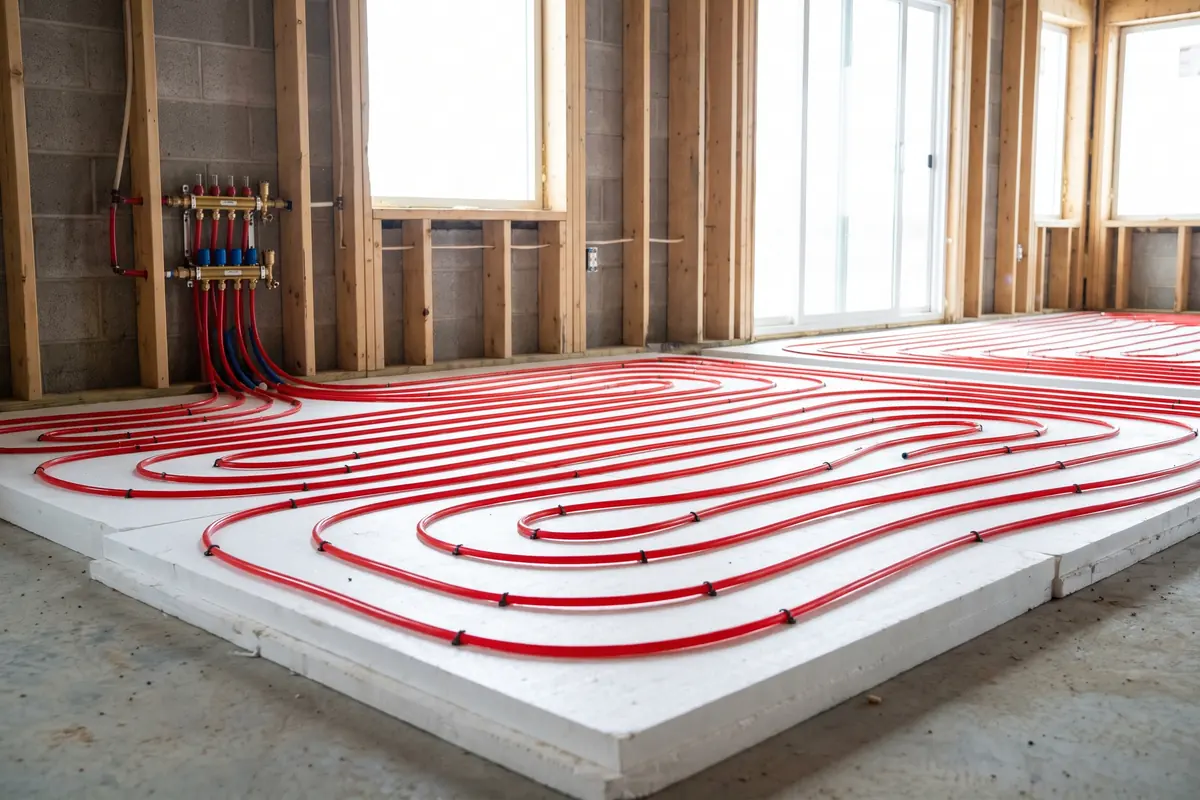
Floor level temperature swing cut from 14 F to under 3 F.
Read the case studyFacility managers do not compliment contractors on charm. They compliment them on being told the truth about what needs replacing and what does not, and on being handed a document at the end.
Reviews are illustrative for this demonstration site. The cube turns on its own, and stops when you hover it or move focus into it.
They measured the static pressure before quoting and told me two of my units did not need replacing. That is the first time a contractor has talked me out of spend.
Our shop is on Fox Street in Denver. Three cities get a dedicated team and a written response time; the rest of the Front Range is covered from the same building.
Also covering Lakewood, Arvada, Westminster, Thornton, Wheat Ridge, Golden and 6 more.Full list

Send us the building, the equipment and the complaint. You get a written response with the load we would run, what we would measure first, and a range before anyone visits.
Or call (303) 555-0148. Mon to Fri 07:00 to 17:00.
Sheet A-00
Specify the finishes and the sheet repaints: the bento tiles, the axonometric hero, every projected drawing, the folder hinges, the lens, the roadmap and the rating cube. A seed lends its hue and its chroma. It never lends its lightness, so the paper stays paper.
Links, buttons, focus rings, the airflow gradient and every blue tone set in every drawing.
Grounds, hairlines, the grey and steel tone sets, the sheet a card is printed on, and the lead, at a tenth of the chroma.
The key cube, drawn from the same projection as the hero. Its faces are the live tone set, so it is a reading of the sheet, not a picture of one.
Replaces the isometric mark in the header and the footer. Only http, https, a site-relative path or a base64 image is accepted.
Revision applies as you type